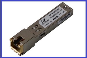
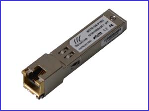
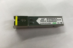
100base-T copper SFP module
BDTR-FB-P1RC Copper Small Form Pluggable (SFP) transceivers are based on the SFP Multi Source Agreement (MSA) . They are compatible with the 100base-T copper SFP module standards as specified in IEEE Std 802.3 .
INFORMATION
1.PRODUCT FEATURES
l Support 10base-T /
100base-Tx
l Hot-pluggable
SFP footprint
l Compact RJ-45 connector
assembly
l RoHS
compliant and lead-free
l Single +3.3V power
supply
l 10/100base-Tx
Fast Ethernet over Cat 5 cable
l Ambient
Operating temperature: -40°C to +85°C
2.PRODUCT DESCRIPTION
transceivers are based on the SFP Multi Source Agreement (MSA) . They are
compatible with the 100base-T copper SFP module standards as specified
in IEEE Std 802.3 . BDTR-FB-P1RC uses the SFP’s RX_LOS pin for link indication.
If pull up SFP’s TX_DISABLE pin, SWITCH
IC be reset.
3. Cable Length
|
Line |
Cable |
Reach |
Host Interface |
|
10base-T |
CAT5 |
200m |
100base-FX |
|
100base-Tx |
CAT5 |
100m |
100base-FX |
4.SFP to Host Connector Pin Out
|
Pin |
Symbol |
Name/Description |
Ref. |
|
1 |
VEET |
Transmitter Ground |
1 |
|
2 |
TFAULT |
Transmitter Fault. Not supported. |
|
|
3 |
TDIS |
Transmitter Disable. Laser output disabled on high or |
2 |
|
4 |
MOD_DEF(2) |
Module Definition 2. Data line for Serial ID. |
3 |
|
5 |
MOD_DEF(1) |
Module Definition 1. Clock line for Serial ID. |
3 |
|
6 |
MOD_DEF(0) |
Module Definition 0. Grounded within the module. |
3 |
|
7 |
Rate Select |
No connection required |
|
|
8 |
LOS |
High indicates no linked. low indicates linked. |
4 |
|
9 |
VEER |
Receiver Ground |
1 |
|
10 |
VEER |
Receiver Ground |
1 |
|
11 |
VEER |
Receiver Ground |
1 |
|
12 |
RD- |
Receiver Inverted DATA out. AC Coupled |
|
|
13 |
RD+ |
Receiver Non-inverted DATA out. AC Coupled |
|
|
14 |
VEER |
Receiver Ground |
1 |
|
15 |
VCCR |
Receiver Power Supply |
|
|
16 |
VCCT |
Transmitter Power Supply |
|
|
17 |
VEET |
Transmitter Ground |
1 |
|
18 |
TD+ |
Transmitter Non-Inverted DATA in. AC Coupled. |
|
|
19 |
TD- |
Transmitter Inverted DATA in. AC Coupled. |
|
|
20 |
VEET |
Transmitter Ground |
1 |
Notes:
1. Circuit ground is
connected to chassis ground
2. PHY disabled on TDIS > 2.0V or open, enabled on TDIS < 0.8V
3. Should be pulled up with 4.7k – 10k Ohms on host
board to a voltage between 2.0 V and 3.6 V. MOD_DEF(0) pulls line low to
indicate module is plugged in.
4. LVTTL compatible with
a maximum voltage of 2.5V.

Figure
1. Diagram of host board connector block pin numbers and names
5. +3.3V
Volt Electrical Power Interface
The
BDTR-FB-P1RC has an input voltage range of 3.3 V +/- 5%. The 4V maximum voltage
is not allowed for continuous operation.
|
+3.3 Volt Electrical Power Interface |
||||||
|
Parameter |
Symbol |
Min |
Typ |
Max |
unit |
Notes/Conditions |
|
Supply Current |
Is |
|
– |
300 |
mA |
1.0W max power over full range of and temperature. See caution note below |
|
Input Voltage |
Vcc |
3.13 |
3.3 |
3.47 |
V |
Referenced to GND |
|
Maximum Voltage |
Vmax |
|
|
4 |
V |
|
|
Surge Current |
Isurge |
|
TBD |
|
mA |
Hot plug above steady state current. See below |
Caution:
Power consumption and surge current are higher than the specified values in the
SFP MSA
6.
Low-Speed Signals
MOD_DEF(1) (SCL)
and MOD_DEF(2) (SDA),
are open drain
CMOS signals (see section VII,
“Serial Communication Protocol”).
Both MOD_DEF(1) and MOD_DEF(2) must be pulled up to host_Vcc
|
Low-Speed Signals, |
|||||
|
Parameter |
Symbol |
Min |
Max |
unit |
Notes/Conditions |
|
SFP Output LOW |
VOL |
0 |
0.5 |
V
|
4.7k measured |
|
SFP Output HIGH |
VOH |
host_Vcc -0.5 |
host_Vcc + 0.3 |
V
|
4.7k to 10k measured at host |
|
SFP Input LOW |
VIL |
0 |
0.8 |
V |
4.7k to 10k pull-up to Vcc, measured at SFP side of connector
|
|
SFP Input HIGH |
VIH |
2 |
Vcc + 0.3 |
V |
4.7k to 10k pull-up to Vcc, measured |
7.High-Speed
Electrical Interface
All
high-speed signals are AC-coupled internally.
|
High-Speed |
||||||
|
Parameter |
Symbol |
Min |
Typ |
Max |
unit |
Notes/Conditions |
|
Line Frequency |
fL |
|
125 |
|
MHz |
5-level encoding, per IEEE 802.3 |
|
Tx Output Impedance |
Zout,TX |
|
100 |
|
Ohm |
Differential, for all frequencies between 1MHz and 125MHz |
|
Rx Input Impedance |
Zin,RX |
|
100 |
|
Ohm |
Differential, for all frequencies between 1MHz and 125MHz |
|
High-Speed |
||||||
|
Parameter |
Symbol |
Min |
Typ |
Max |
unit |
Notes/Conditions |
|
Single ended data input swing |
Vinsing |
250 |
|
1200 |
mV
|
Single ended |
|
Single ended data output swing |
Voutsing |
350 |
|
800 |
mV |
Single ended |
|
Rise/Fall Time |
Tr,Tf |
|
– |
|
psec |
20%-80% |
|
Tx Input Impedance |
Zin |
|
50 |
|
Ohm |
Single ended |
|
Rx Output Impedance |
Zout |
|
50 |
|
Ohm |
Single ended |
8.General
Specifications
|
General |
||||||
|
Parameter |
Symbol |
Min |
Typ |
Max |
unit |
Notes/Conditions |
|
Data Rate |
BR |
10 |
|
100 |
Mb/sec |
IEEE 802.3 See Notes 1,2 below |
Notes: 1. Clock tolerance is +/- 50 ppm
9.Environmental
Specifications
Automatic crossover detection
is enabled. External crossover cable is
not required
|
Environmental Specifications |
||||||
|
Parameter |
Symbol |
Min |
Typ |
Max |
unit |
Notes/Conditions |
|
Operating Temperature |
Top |
-40 |
|
85 |
°C |
Case temperature |
|
Storage Temperature |
Tsto |
-40 |
|
85 |
°C |
Ambient temperature |
10.
Serial Communication Protocol
All
WINTOP SFPs support the 2-wire serial communication protocol outlined in the
SFP MSA. These SFPs use an MCU, can be accessed with address of A0h.
|
Serial Bus Timing, Requirements |
||||||
|
Parameter |
Symbol |
Min |
Typ |
Max |
unit |
Notes/Conditions |
|
I 2C Clock Rate |
|
0 |
|
200,000 |
Hz |
|
11. Mechanical Specifications (Unit:mm)

Related Products
Send an Inquiry
Tell us your required quantity, destination country, and any technical requirements. We'll reply within 12 hours.