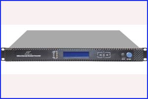
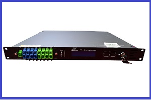
1550nm External Modulated Optical Transmitter
The optical transmitter is a 1550nm DFB laser external modulated transmitter. It is specially developed for the CATV signal that satisfies HFC network, and the long-distance transmission of cable phone and cable data.
INFORMATION
Description
The external modulated transmitter is
specially developed for the CATV signal that satisfies HFC network, and the
long-distance transmission of cable phone and cable data.This optical transmitter is a 1550nm DFB laser. The external modulated transmitter can be managed by console or WEB managed, easily mornitor and configure.
Working principle
It has 7 function modules:
RF control, DFB laser, optical modulator, SBS control, CSO control,
communication/display control and power supply.
Automatic gain control
circuit (AGC) or manual gain control circuit (MGC) amplifies the RF signal. AGC
or MGC control makes the optical modulator maintain a suitable input level. Use
the detected RF root-meansquare(RMS)-total
power to calculate the optical modulation index(OMI).
In general we
recommend using the AGC function, and special users can use the MGC function to
adjust the CNR/CSO/CTB performance indexes.
The core of transmitter is
the optical modulator. The 1550nm signal input the optical modulator, make the
laser intensity changed follow the external RF signal voltage, and then
generate the AM optical signal.
Stimulated Brillouin
Scattering (SBS) occurs, when the optical input power is greater than a certain
threshold value. SBS generate the lower frequency backscattered light which
will attenuate the transmission light and return to the laser while destroying
its performance. Causing optical power fluctuation, generates large noise, and
seriously deteriorates the system carrier to noise ratio (CNR). To improve the
SBS threshold, this optical transmitter adopts SBS control technology which is
independent researched and developed by ourselves. The threshold value can be
set up to 19dBm.
1) Detect whether the laser is
normal working. Once the output optical power is 2dB lower than standard power,
alarm will be set off.
2) Detect CSO distortion to
optimize the bias point of the optical modulator. For working normal the
detector circuit needs at least two carrier signal inputs with an interval of
24MHz. There is a CSO initialization program in the boot
process. If the CSO install failed, the RF indicator
will flash red, see details in 6.2
Troubleshooting.
Block Diagram

1.3 Product
Applications
• High-performance
long-distance transmission
• High-power distribution
network
• Redundancy loop
architecture
• FTTx network
• RFOG application
• DWDM network
Technique Parameters
Optical Parameters
Item
Unit
Value
Optical Wavelength
nm
1545~1560 (or
specified by the user)
Side-mode Suppression ratio
dB
>30
Relative Intensity Noise
dB/Hz
<-160
Wavelength Adjustment Range
GHz
+/-50GHz
Optical Power
dBm
2*5, 2*7, 2*8, 2*9, 2*10
SBS Threshold Value
dBm
+13~+19
(Continuously adjustable)
Laser Linewidth
MHz
0.3
|
Item |
Unit |
|
|
Optical Wavelength |
nm |
1545~1560 (or |
|
Side-mode Suppression ratio |
dB |
>30 |
|
Relative Intensity Noise |
dB/Hz |
<-160 |
|
Wavelength Adjustment Range |
GHz |
+/-50GHz |
|
Optical Power |
dBm |
2*5, 2*7, 2*8, 2*9, 2*10 |
|
SBS Threshold Value |
dBm |
+13~+19 |
|
Laser Linewidth |
MHz |
0.3 |
Technical Specification
Item
Unit
Technical
Parameters
RF range
MHz
47~1003
RF flatness
dB
+/-0.75
RF return loss
dB
>16
RF input impedance
Ω
75
RF input connector type
F type
Rated input level
dBμV
80
Input level range
dBμV
78~96 (AGC mode, modulating signal)
AGC control range
dB
+3~-3
MGC adjustable range
dB
0~15
Optical connector
SC/APC, FC/APC
Operating temperature
°C
-5~45
Storage temperature
°C
-30~+70
Power Source Specification
V
90~265VAC
36~72VDC
Consumption
W
≤60
Dimension
mm
483(L) × 455(W) × 44(H)
Total Weight
kg
5.5
|
Item |
Unit |
Technical |
|
RF range |
MHz |
47~1003 |
|
RF flatness |
dB |
+/-0.75 |
|
RF return loss |
dB |
>16 |
|
RF input impedance |
Ω |
75 |
|
RF input connector type |
|
F type |
|
Rated input level |
dBμV |
80 |
|
Input level range |
dBμV |
78~96 (AGC mode, modulating signal) |
|
AGC control range |
dB |
+3~-3 |
|
MGC adjustable range |
dB |
0~15 |
|
Optical connector |
|
SC/APC, FC/APC |
|
Operating temperature |
°C |
-5~45 |
|
Storage temperature |
°C |
-30~+70 |
|
Power Source Specification |
V |
90~265VAC |
|
36~72VDC |
||
|
Consumption |
W |
≤60 |
|
Dimension |
mm |
483(L) × 455(W) × 44(H) |
|
Total Weight |
kg |
5.5 |
Panel Interface and Menu System Description
Front Panel

|
1 |
Power |
2 |
AGC |
3 |
RF |
|
4 |
Laser |
5 |
LCD |
6 |
ESC |
|
7 |
UP |
8 |
DOWN |
9 |
Enter |
|
10 |
RF |
11 |
-20dB |
|
|
Rear Panel

|
1 |
Ground |
2 |
Power |
3 |
Fan |
|
4 |
RF |
5 |
RS232 |
6 |
LAN |
|
7 |
Optical |
8 |
Optical |
|
|
Power Module
220V Power Module

|
1 |
Mounting |
2 |
220V |
3 |
Fuse |
|
4 |
Power |
|
|
|
|
48V Power Module

|
1 |
Mounting |
2 |
+ |
3 |
– |
WEB Network Management
Open the IE
browser, type the IP address and enter the interface as follows:


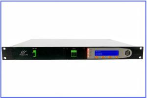
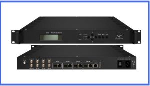
Related Products
Send an Inquiry
Tell us your required quantity, destination country, and any technical requirements. We'll reply within 12 hours.