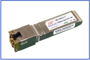
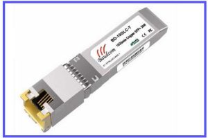
10GBASE-T SFP+ Copper Transceiver for 10 Gigabit Ethernet
10gbase-t SFP module supports data rates up to 10Gbps and is fully compliant with IEEE 802.3 standards for both 10GBASE-T and 1000BASE-T, ensuring backward compatibility
INFORMATION
Unlock the power of 10-Gigabit Ethernet with our high-performance 10GBASE-T Copper SFP+ Transceiver. This module provides a flexible and cost-effective solution for connecting SFP+ ports on switches, routers, and network interface cards to standard RJ45 Ethernet cables.
Designed for seamless integration, it supports data rates up to 10Gbps and is fully compliant with IEEE 802.3 standards for both 10GBASE-T and 1000BASE-T, ensuring backward compatibility with existing Gigabit Ethernet infrastructure. Achieve reliable connections up to 30 meters using Category 6A (or higher) cabling, making it ideal for top-of-rack switching and short-run data center links.
Product Features
Ø Up to 10Gbps bi-directional data links
Ø RJ45 Max 30m
Ø Fully metallic enclosure for low EMI
Ø Compact RJ-45 Connector assembly
Ø Hot-pluggable SFP footprint
Ø Low power dissipation
Ø Extended case temperature: 0℃ to 70℃
Ø RoHS compliant and Lead Free
Applications
10 Gigabit Ethernet
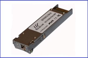
Product Description
The BD-10GLC-T is Copper Small Form pluggable (SFP) transceiver, which is based on SFP multi-sourcing agreement (MSA). It is compatible with the 10GBASE-T and 1000BASE-T standards as specified in IEEE Std 802.3.The 1000BASE-T physical layer IC(PHY) can be accessed via I2C,allowing access to LIMITED PHY settings and features.
Regulatory Compliance
The transceivers are Class 1 Laser Products comply with FDA regulations. Meet Class 1 eye safety requirements of EN 60825 and the electrical safety requirements of EN 60950.
+3.3V Volt Electrical Power Interface
The BD-10GLC-T has an input voltage range of 3.3V +/-5%,The 4 V maximun voltage is not allowed for continuous operation.
|
Parameter |
Symbol |
Min. |
Typ |
Max |
Units |
Notes/Conditions |
|
Supply Current |
Is |
|
|
600 |
mA |
1.2W max power over full range of voltage and temperature.see caution note below |
|
Power Supply Voltage |
Vcc |
3.13 |
3.3 |
3.47 |
v |
Referebced to GND |
|
Maximum Voltage |
Vmax |
|
|
4 |
v |
|
|
Surge Current |
Isurge |
|
|
550 |
mA |
Hot plug above steady state current,See caution note below |
Caution:Power consumption and surge current are higher than the specified values in the SFP MSATable 1.+3.3 Volt electrical power interface
Low-Speed Signals
|
Parameter |
Symbol |
Min. |
Max |
Units |
Notes/Conditions |
|
SFP Output LOW |
VOL |
0 |
0.5 |
V |
4.7k to 10k pull-up to host Vcc,measured at host side of connector |
|
SFP Output HIGH |
VOH |
Host Vcc-0.5 |
Host Vcc+0.3 |
V |
4.7k to 10k pull-up to host Vcc,measured at host side of connector |
|
SFP Input LOW |
VIL |
0 |
0.8 |
V |
4.7k to 10k pull-up to Vcc,measured at SFP side of connector |
|
SFP Input HIGH |
VIH |
2 |
Vcc+0.3 |
V |
4.7k to 10k pull-up to Vcc,measured at SFP side of connector |
Table 2. Low-speed signals, electronic characteristics
High-Speed Electrical Interface
ALL high-speed signals are AC-coupled internally
(1)High-speed Electrical Interface Transmission Line-SFP
|
Parameter |
Symbol |
Min. |
Typ |
Max |
Units |
Notes/Conditions |
|
Line Frequency |
fL |
10 |
125 |
1000 |
MHZ |
5-level encoding,per IEEE 802.3 |
|
Tx Output Impedance |
Zout,TX |
|
100 |
|
Ohm |
Differential,for all frequencies between 1MHz and 125MHz |
|
Rx Input Impedance |
Zin,RX |
|
100 |
|
Ohm |
Differential,for all frequencies between 1MHz and 125MHz |
Table 3. High-speed electrical interface,transmission line-SFP
(2)High-speed Electrical Interface,Host-SFP
|
Parameter |
Symbol |
Min. |
Typ |
Max |
Units |
Notes/Conditions |
|
Single ended data input swing |
Vinsing |
180 |
|
700 |
mV |
Single ended |
|
Single ended data output swing |
Voutsing |
350 |
|
850 |
mV |
Single ended |
|
Rise/Fall Time |
Tr,Tf |
|
175 |
|
psec |
20%-80% |
|
Tx Input Impedance
|
Zin |
|
50 |
|
Ohm |
Single ended |
|
Rx Output Impedance |
Zout |
|
50 |
|
Ohm |
Single ended |
Table 4. High-speed electrical interface,host-SFP
General Specifications
|
Parameter |
Symbol |
Min. |
Typ |
Max |
Units |
Notes/Conditions |
|
Data Rate |
BR |
10 |
|
10000 |
Mb/sec |
IEEE 802.3 compatible.See Notes 2 through 4 below |
|
Tx Output Impedance |
L |
|
|
100 |
m |
Category 5 UTP.BER<10-12 |
Table 5. General specifications
Note:
1.Clock tolerance is +/- 50 ppm
2.By default,the CLBD-10GLC-T is a full duplex device in preferred master mode
3.Automatic crossover detection is enabled. External crossover cable is not required
4. Multi- BASE-T operation requires the host system to have an SGMII interface with no clocks, and the module PHY to be configured per Applications Note AN-2036.With a SERDES that does not support SGMII,the module will operate at single rate only.
Environmental Specifications
The BD-10GLC-T has an extended range from 0℃ to +70℃ case temperature as specified in Table.
|
Parameter |
Symbol |
Min. |
Typ |
Max |
Units |
Notes/Conditions |
|
Operating Temperature |
Top |
0 |
|
70 |
|
Case temperature |
|
Storage Temperature |
Tsto |
0 |
|
70 |
|
Ambient temperature |
Table 6. Environmental specifications
Pin Descriptions
|
Pin |
Symbol |
Description |
Ref. |
|
1 |
VEET |
Transmitter Ground (Common with Receiver Ground) |
8.1 |
|
2 |
TFAULT |
Transmitter Fault. Not supported. |
|
|
3 |
TDIS |
Transmitter Disable. Laser output disabled on high or open. |
8.2 |
|
4 |
MOD_DEF(2) |
Module Definition 2. Data line for Serial ID. |
8.3 |
|
5 |
MOD_DEF(1) |
Module Definition 1. Clock line for Serial ID. |
8.3 |
|
6 |
MOD_DEF(0) |
Module Definition 0. Grounded within the module. |
8.3 |
|
7 |
Rate Select |
No connection required |
|
|
8 |
LOS |
Grounded |
8.4 |
|
9 |
VEER |
Receiver Ground (Common with Transmitter Ground) |
8.1 |
|
10 |
VEER |
Receiver Ground (Common with Transmitter Ground) |
8.1 |
|
11 |
VEER |
Receiver Ground (Common with Transmitter Ground) |
8.1 |
|
12 |
RD- |
Receiver Inverted DATA out. AC Coupled. |
|
|
13 |
RD+ |
Receiver Non-inverted DATA out. AC Coupled. |
|
|
14 |
VEER |
Receiver Ground (Common with Transmitter Ground) |
8.1 |
|
15 |
VCCR |
Receiver Power Supply |
|
|
16 |
VCCT |
Transmitter Power Supply |
|
|
17 |
VEET |
Transmitter Ground (Common with Receiver Ground) |
8.1 |
|
18 |
TD+ |
Transmitter Non-Inverted DATA in. AC Coupled. |
|
|
19 |
TD- |
Transmitter Inverted DATA in. AC Coupled. |
|
|
20 |
VEET |
Transmitter Ground (Common with Receiver Ground) |
8.1 |
Table 7. SFP to host connector pin assignments and descriptionsNotes:
1. Circuit ground is connected to chassis ground.
2.PHY disabled on TDIS>2.0V or open,enabled on TDIS<0.8V.
3.Should be pulled up with 4.7k – 10k Ohms on host board to a voltage between 2.0V and 3.6V. MOD_DEF(0) pulls line low to indicate module is plugged in.
Serial Communication Protocol
BD-10GLC-T supports the 2-wire serial communication protocol outlined in the SFP MSA.
The physical layer IC can also be accessed via the 2-wire serial bus at address Ach.
|
Parameter |
Symbol |
Min. |
Typ |
Max |
Units |
Notes/Conditions |
|
IC Clock Rate |
|
0 |
|
100000 |
Hz |
|
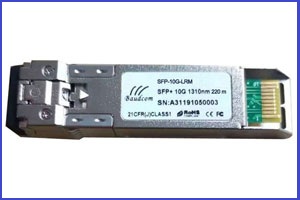
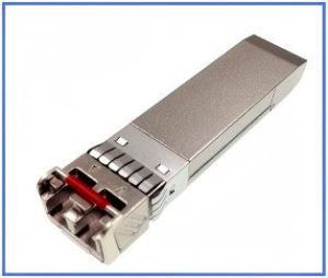
Related Products
Send an Inquiry
Tell us your required quantity, destination country, and any technical requirements. We'll reply within 12 hours.