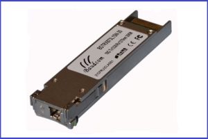
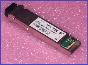
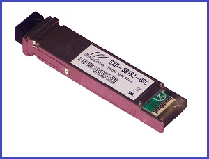
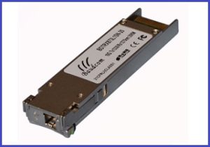
10G XFP BIDI Transceiver
10G XFP BIDI Modules,single fiber,WDM,10KM,20KM,40KM,80KM
INFORMATION
Features
¨ Supports 9.95Gb/s to 10.5Gb/s bit rates
¨ Hot-pluggable XFP footprint
¨ Maximum link length of
¨ 1270/1330nm DFB laser Transmitter and 1330/1270nm Receiver
¨ XFP MSA package with LC connector
¨ No reference clock required
¨
¨ +3.3V,+1.8V power supply
¨ Power dissipation <2W
¨ Compatible with RoHS
¨ Built-in digital diagnostic functions
¨ Temperature range
Applications
¨ 10GBASE-LR at 10.3125Gbps
¨ 10GBASE-LW at 9.953Gbps
¨ 10GBASE-BX
¨ 10GBASE-BX
Description
Baudcom
The transceiver module comprises a transmitter with a 1270/1330nm DFB laser transmitter, an integrated 1330/1270nm detector preamplifier(IDP) mounted in an optical header and a limiting post-amplifier IC. Transmitter and receiver are separate within a wide temperature range of
Absolute Maximum Ratings
|
Parameter |
Symbol |
Min |
Max |
Unit |
Ref. |
|
Storage Ambient |
|
-40 |
+85 |
℃ |
|
|
Powered case |
|
0 |
+70 |
℃ |
|
|
Operating Relative Humidity |
RH |
|
85 |
% |
|
|
|
Vcc3 |
0 |
3.6 |
V |
|
|
|
|
0 |
1.98 |
V |
|
Any stress beyond the maximum ratings can result in permanent damage. The device specifications are guaranteed only under the recommended operating conditions.
Electrical Characteristics
|
Parameter |
Symbol |
Min |
Typ |
Max |
Unit |
Note |
||
|
Operating |
Tc |
0 |
|
+70 |
℃ |
|
||
|
Power Supply Voltage @ 3.3V |
Vcc3 |
3.13 |
3.3 |
3.47 |
V |
|
||
|
Power Supply Voltage @ 1.8V |
|
1.62 |
1.8 |
1.98 |
|
|
||
|
Module total power |
P |
|
|
2 |
W |
|
||
|
Transmitter |
||||||||
|
Input differential impedance |
Rin |
|
100 |
|
Ω |
1 |
||
|
Differential data input swing |
Vin,pp |
120 |
|
820 |
mV |
|
||
|
Transmit Disable Voltage |
VD |
2.0 |
|
VCC |
V |
|
||
|
Transmit Enable Voltage |
VEN |
0 |
|
0.8 |
V |
|
||
|
Transmit Disable Assert Time |
|
|
|
10 |
us |
|
||
|
Receiver |
||||||||
|
Differential data output swing |
Vout,pp |
340 |
|
850 |
mV |
|
||
|
Data output rise time |
tr |
|
|
38 |
ps |
2 |
||
|
Data output fall time |
tf |
|
|
38 |
ps |
2 |
||
|
LOS Fault |
VLOS fault |
Vcc – 0.5 |
|
VccHOST |
V |
3 |
||
|
LOS Normal |
VLOS norm |
GND |
|
GND+0.5 |
V |
3 |
||
|
Power Supply Rejection |
PSR |
See Note 3 below |
4 |
|||||
Notes:
1. After internal AC coupling.
2. 20 – 80 %
3. Loss Of Signal is open collector to be pulled up with a 4.7k – 10kohm resistor to 3.15 – 3.6V. Logic 0 indicates normal operation; logic 1 indicates no signal detected.
4. Per Section
Optical Characteristics
|
Parameter |
Symbol |
Min |
Typ |
Max |
Unit |
Ref. |
|
Transmitter |
||||||
|
Optical output Power |
P |
-2 |
|
2 |
dBm |
|
|
Optical Wavelength |
λ |
1260 |
1270 |
1280 |
nm |
|
|
1320 |
1330 |
1340 |
||||
|
Side Mode Suppression Ratio |
SMSR |
30 |
|
|
dB |
|
|
Optical Extinction Ratio |
ER |
3.5 |
|
|
dB |
1 |
|
Average Launch power of OFF transmitter |
POFF |
-30 |
|
|
dBm |
|
|
Tx Jitter |
Txj |
Compliant with each standard requirements |
|
|||
|
Receiver |
||||||
|
Receiver Sensitivity |
RSENS |
|
|
-14 |
dBm |
2 |
|
Receiver Sensitivity in OMA |
RSENS |
|
|
-12.5 |
dBm |
2 |
|
Maximum Input Power |
PMAX |
+0.5 |
|
|
dBm |
|
|
Optical Center Wavelength |
λC |
1320 |
|
1340 |
nm |
|
|
1260 |
|
1280 |
||||
|
LOS De-Assert |
LOSD |
|
|
-18 |
dBm |
|
|
LOS Assert |
LOSA |
-30 |
|
|
dBm |
|
|
LOS Hysteresis |
|
1 |
|
5 |
dB |
|
Notes:
1, PRBS 231-1 test pattern @10.3125Gbps.
2, PRBS 231-1 test pattern @10.3125Gbps, BER≤10-12.
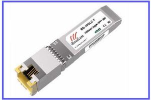
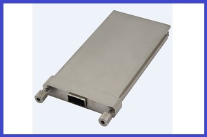
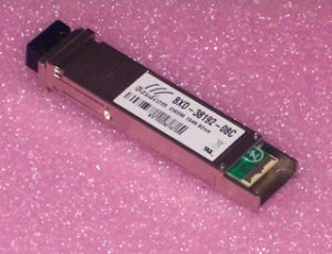
Related Products
Send an Inquiry
Tell us your required quantity, destination country, and any technical requirements. We'll reply within 12 hours.