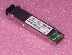
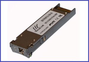
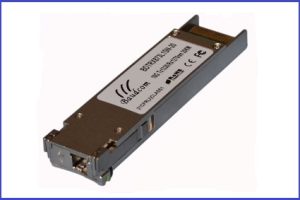
CWDM 10G XFP Optical Module
CWDM 10G XFP Optical Transceiver,up to 80KM,MSA
INFORMATION
Description
Baudcom CWDM
XFP Transceiver exhibits excellent wavelength stability, supporting operation
at 100 GHz channel, cost effective module. It is designed for
The
transceiver consists of two sections: The transmitter section incorporates a
colded EML laser. And the receiver section consists of a APD photodiode
integrated with a TIA. All modules satisfy class I laser safety requirements. Baudcom
CWDM XFP transceiver provides an enhanced monitoring interface, which allows real-time
access to device operating parameters such as transceiver temperature, laser
bias current, transmitted optical power, received optical power and transceiver
supply voltage.
Features
¨ Wavelength
selectable to ITU-T standards covering CWDM grid
¨ XFP MSA Rev
4.5 Compliant
¨ Data
rate from 9.95Gbps to 11.1Gbps
¨ No
Reference Clock required
¨ Cooled
EML and APD receiver
¨ Maximum
link length up to
fiber)
¨ Low
Power Dissipation 3.5W Maximum
¨ XFI and
lineside loopback Mode Supported
¨ -5oC to
70oC Operating Case Temperature
¨ Diagnostic
Performance Monitoring of module temperature,
Supply
Voltages, laser bias current, transmit optical power, and receive optical power
¨ RoHS6
compliant (lead free)
Applications
¨ SONET
OC-192& SDH STM 64
¨ CWDM
¨ CWDM
¨ CWDM
Networks
¨ CWDM
Transmitter
Specifications – Optical
|
Parameter
|
Symbol
|
Min
|
Typical
|
Max
|
Unit
|
|
Center
|
c
|
|
|
|
nm
|
|
Center
|
D
|
|
c
|
|
nm
|
|
Optical Transmit Power
|
|
0
|
–
|
+3
|
dBm
|
|
Optical Transmit Power (disabled)
|
PTX_DIS
|
–
|
–
|
-30
|
dBm
|
|
Extinction Ratio
|
ER
|
8.2
|
–
|
–
|
dB
|
|
Jitter Generation(P-P)
|
JG P-P
|
–
|
–
|
0.1
|
UI
|
|
Jitter Generation(RMS)
|
JG RMS
|
–
|
–
|
0.01
|
UI
|
|
Spectral Width (-20dB)
|
Δλ20
|
–
|
–
|
0.3
|
nm
|
|
Side
|
SMSR
|
30
|
–
|
–
|
dB
|
|
Dispersion
|
DP
|
–
|
–
|
3
|
dB
|
|
Relative
|
RIN
|
–
|
–
|
-130
|
dB/Hz
|
|
Eye
|
Compliant
|
||||
Note:
1. Wavelength stability is achieved within 60 seconds
(max) of power up.
2. BER=10^-12;
PRBS 2^31-1@10.3125Gbps
Transmitter
Specifications – Electrical
|
Parameter
|
Symbol
|
Min
|
Typical
|
Max
|
Unit
|
|
Input differential impedance
|
Rim
|
–
|
100
|
–
|
Ω
|
|
Differential data Input
|
VtxDIFF
|
120
|
–
|
850
|
mV
|
|
Transmit Disable Voltage
|
VD
|
2.0
|
–
|
Vcc3+0.3
|
V
|
|
Transmit Enable Voltage
|
Ven
|
0
|
–
|
+0.8
|
V
|
|
Transmit
|
Vn
|
–
|
–
|
10
|
us
|
Specifications – Optical
|
Parameter
|
Symbol
|
Min
|
Typical
|
Max
|
Unit
|
|||
|
Maximum Input Power
|
RX-overload
|
-7
|
–
|
–
|
dBm
|
|||
|
Input
|
λ
|
|
–
|
|
nm
|
|||
|
Reflectance
|
Rrx
|
–
|
–
|
-27
|
dB
|
|||
|
Loss of Signal Asserted
|
LOS_A
|
-34
|
–
|
–
|
dBm
|
|||
|
LOS De-Asserted
|
LOS_D
|
–
|
–
|
-24
|
dBm
|
|||
|
LOS Hysteresis
|
LOS_H
|
0.5
|
–
|
–
|
dB
|
|||
|
Receiver Sensitivity
|
||||||||
|
Data rate (Gb/s)
|
BER
|
Dispersion (ps/nm)
|
Sensitivity
|
Power Penalty at
|
||||
|
9.95 ~10.3125
|
1e-12
|
-500 to 1450
|
-24
|
2
|
||||
|
10.7 ~11.1
|
1e-4
|
-500 to 1300
|
-27
|
2
|
||||
|
OSNR Performance
|
||||||||
|
Data rate (Gb/s)
|
BER
|
Dispersion (ps/nm)
|
Min OSNR Back-to-back
|
Max OSNR Penalty
|
||||
|
9.95 ~10.3125
|
1e-12
|
-500 to 1450
|
24
|
4
|
||||
|
10.7 ~11.1
|
1e-4
|
-500 to 1300
|
16
|
4
|
||||
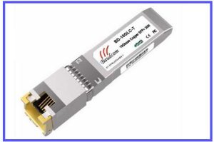
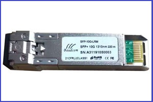
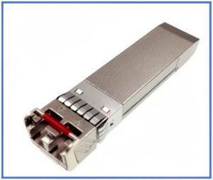
Related Products
Send an Inquiry
Tell us your required quantity, destination country, and any technical requirements. We'll reply within 12 hours.