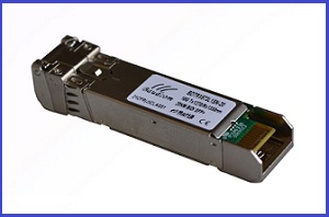
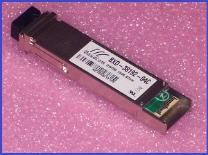
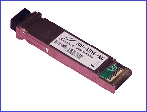
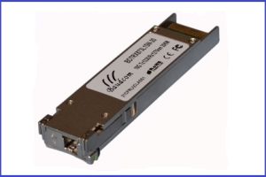
10km Bi-Directional SFP+ Optical Transceiver
10G Bi-Directional SFP+ Optical Transceiver,10KM,20KM,40KM,80KM
INFORMATION
Features
¨ Simplex LC Connector Bi-Directional SFP+ Optical Transceiver
¨ Compliant with SFF-8431,SFF-8432 and IEE802.3ae
¨ Up to
9/125um SMF
¨ Two types:
A:1270nm DFB Laser transmitter,1330nm receiver
B:1330nm DFB Laser transmitter,1270nm receiver
¨ Digital Diagnostic SFF-8472 Compliant
¨  Operating case temperature 0 ~
¨ RoHS6 compliant (lead free)
Applications
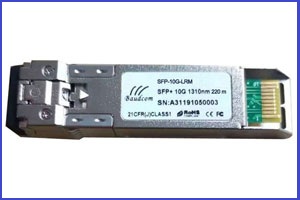
¨ 10GBASE-LR at 10.3125Gbps
¨ Other Optical Links
Product description
The BDTRX837L1SN-10 & BDTRX873L1SN-10 series
single mode transceiver is small form factor pluggable module for duplex
optical data communications such as 10GBASE-LR/LW defined by IEEE 802.3ae. It
is with the SFP+ 20-pin connector to allow hot plug capability.
The 10G SFP+ module BDTRX873L1SN-10 is designed for
single mode fiber and operates at a nominal wavelength of 1270nm; BDTRX837L1SN-10
module is designed for single mode fiber and operates at a nominal wavelength
of 1330nm. The transmitter section uses a multiple quantum well DFB, which is
class 1 laser compliant according to International Safety Standard IEC-60825.
The receiver section uses an integrated InGaAs
detector preamplifier (IDP) mounted in an optical header and a limiting
post-amplifier IC.
Absolute Maximum Ratings
These
values represent the damage threshold of the module. Stress in excess of any of the individual
Absolute Maximum Ratings can cause immediate catastrophic damage to the module
even if all other parameters are within Recommended Operating Conditions.
|
Parameters |
Symbol |
Min. |
Max. |
Unit |
|
Supply Voltage |
VCC |
-0.5 |
+3.6 |
V |
|
Storage Temperature |
Tc |
-40 |
+85 |
°C |
|
Operating Case |
Tc |
0 |
+70 |
°C |
|
Relative Humidity |
RH |
0 |
85 |
% |
Recommended Operating Conditions
|
Parameter |
Symbol |
Min. |
Typical |
Max |
Unit |
|
Supply Voltage |
VCC |
3.0 |
3.3 |
3.6 |
V |
|
Supply current |
Icc |
|
200 |
300 |
mA |
|
Operating Case |
TC |
0 |
25 |
70 |
°C |
|
Module Power Dissipation |
Pm |
– |
0.7 |
1.1 |
W |
Notes:
1. Supply current is
shared between VCCTX and VCCRX.
2. In-rush is defined as
current level above steady state current requirements.
Optical characteristics (BDTRX873L1SN-10, 1270 DFB & PIN/TIA)
|
Parameter |
Symbol |
Min. |
Typical |
Max |
Unit |
Ref. |
|
Transmitter |
||||||
|
Optical Wavelength |
λC |
1260 |
1270 |
1280 |
nm |
|
|
Side Mode Suppress Ratio |
SMSR |
30 |
|
|
dB |
|
|
Spectral Width(-20dB) |
Δλ |
|
|
1 |
nm |
|
|
Average Output Power |
Pop |
-8.2 |
|
0.5 |
dBm |
1 |
|
Extinction Ratio |
ER |
3.5 |
|
|
dB |
|
|
Eye Mask |
|
Compliant with IEEE 802.3 |
||||
|
Transmitter and Dispersion Penalty |
TDP |
|
|
3.2 |
dB |
|
|
Average Power of OFF Transmitter |
|
|
|
-30 |
dBm |
|
|
Relative Intensity Noise |
RIN |
|
|
-128 |
dB/Hz |
|
|
Receiver |
||||||
|
Average Receiver Power |
RSENS |
|
|
-14.1 |
dBm |
1,2 |
|
Receiver Overload |
PMAX |
|
|
+0.5 |
dBm |
|
|
Centre |
λC |
1320 |
|
1340 |
nm |
|
|
LOS De-Assert |
LOSD |
|
|
-15 |
dBm |
|
|
LOS Assert |
LOSA |
-30 |
|
|
dBm |
|
|
LOS Hysteresis |
|
0.5 |
|
|
dB |
|
Notes:
1. Average Receiver Power (Min) is informative and not
the principal indicator of signal strength. A received power below this value
cannot be compliant.
2. Measured with a PRBS231-1 test pattern @10.3125Gbps,
BER≦10-12
Optical characteristics (BDTRX837L1SN-10, 1330 DFB &
PIN/TIA)
|
Parameter |
Symbol |
Min. |
Typical |
Max |
Unit |
Ref. |
|
Transmitter |
||||||
|
Optical Wavelength |
λC |
1320 |
1330 |
1340 |
nm |
|
|
Side Mode Suppress Ratio |
SMSR |
30 |
|
|
dB |
|
|
Spectral Width(-20dB) |
Δλ |
|
|
1 |
nm |
|
|
Average Output Power |
Pop |
-8.2 |
|
0.5 |
dBm |
1,2 |
|
Extinction Ratio |
ER |
3.5 |
|
|
dB |
|
|
Eye Mask |
|
Compliant with IEEE 802.3 |
||||
|
Transmitter and Dispersion Penalty |
TDP |
|
|
3.2 |
dB |
|
|
Average Power of OFF Transmitter |
|
|
|
-30 |
dBm |
|
|
Relative Intensity Noise |
RIN |
|
|
-128 |
dB/Hz |
|
|
Receiver |
||||||
|
Average Receiver Power |
RSENS |
|
|
-14.1 |
dBm |
2,3 |
|
Receiver Overload |
PMAX |
|
|
+0.5 |
dBm |
|
|
Centre Wavelength |
λC |
1260 |
|
1270 |
nm |
|
|
LOS De-Assert |
LOSD |
|
|
-15 |
dBm |
|
|
LOS Assert |
LOSA |
-30 |
|
|
dBm |
|
|
LOS Hysteresis |
|
0.5 |
|
|
dB |
|
Notes:
1.
Output is coupled into a 9/125um SMF.
2. Average Receiver Power (Min) is informative and
not the principal indicator of signal strength. A received power below this
value cannot be compliant.
3. Measured with a PRBS231-1 test pattern @10.3125Gbps, BER≦10-12

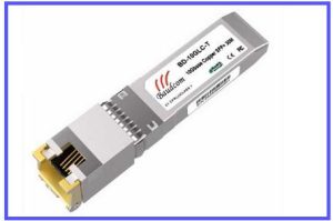
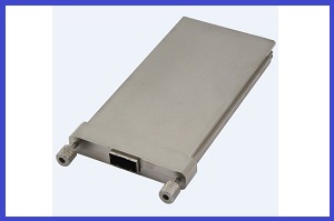
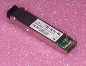
Related Products
Send an Inquiry
Tell us your required quantity, destination country, and any technical requirements. We'll reply within 12 hours.